ID Field - Required. An alphanumeric ID for the record.
Location Field - Optional. If you select a location it filters both the Project and Building fields.
Project Field - Optional. Select a project to associate with the record. If a location is selected the dropdown here only shows projects associated with the location.
Building Field - Optional. Select a building to associate with the record. If a location is selected the dropdown here only shows buildings associated with the location.
Attached Record Field - If the PMWeb Viewer record was created from the Document Manager or from the Attachments Tab of any record, the linked record information will appear in this field. Click the field label hyperlink to navigate to the linked record.
BIM Model Field - The dropdown displays a list of records in the Model Manager. Select one to mark that the PMWeb Viewer record is associated with the Model Manager one.
File Management Section - The file selected here will appear in the Redlining Tab Drawing Area. Allowed 2D file formats are: pdf, gif, bmp, jpg, jpeg, dxf. Files may be pulled from those already stored in the PMWeb Document Manager or may be uploaded directly into the PMWeb Viewer record. If you select the Document Manager radio button and click the Browse button the Files Lookup Dialog opens. If you select the Upload radio button and click the Browse button the browse file dialog for your operating system opens.
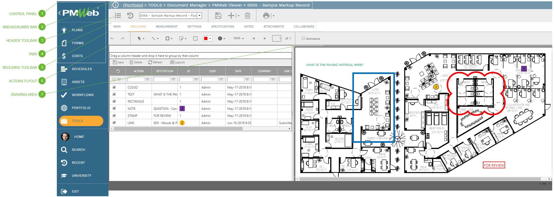
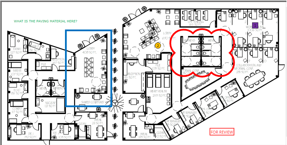
Redlining Tab - Use this tab to draw on, and add symbols and notes to, 2D graphic files.
Settings Tab - This tab is used to view and edit the drawing permissions granted to companies and users for this record. New PMWeb Viewer records default to the configuration in PMWeb Viewer Settings but may be edited. See the help topic for PMWeb Viewer Settings to learn about these options.
Select Cursor - Used to select items on the screen
Pan Cursor - Used to drag the viewing area on the screen
Line Buttons
Straight Line Tool - With this selected, click once in the drawing to define a beginning point and click again to define the ending point of a straight line
Polyline Tool - With this selected, each click in the drawing are defines a new, connected, line segment
Shape Buttons
Rectangle Tool - With this selected, click and drag in the drawing area to define a rectangle
Ellipse Tool - With this selected, click and drag in the drawing are to define an ellipse
Symbol Buttons
Note Tool - When you select this tool a dialog opens. Enter your note in the text field, click the Save button, and then click somewhere in the drawing area to place the note. A note symbol appears on the drawing. When the symbol is clicked, the note is displayed.
Text Tool - When you select this tool a dialog opens. Enter your note in the text field, click the Save button, and then click somewhere in the drawing area to place the note. The text appears on the drawing.
Stamp Tool - When you select this tool a dialog opens. Select one of your custom stamps in the dialog and then click somewhere in the drawing area to place it.
Link Tool - When you select this tool a dialog opens. Select a PMWeb record in the dialog and then click somewhere in the drawing area to place it. A linked record symbol appears on the drawing. When the symbol is clicked, the user navigates to the PMWeb record.
Cloud Tool - With this tool selected, click and drag in the drawing area to define a cloud area.
Color Selector - Select a color to be applied to your next action
Line Weight Selector - Drag the slider to select a line weight for your next action
Zoom Control - Drag the slider to zoom in or out on the image or click the 100% button to reset the view.
Page Controls - If this is a multi-page file, use these controls to navigate through pages
Autosave Checkbox - With this box checked, edits to the drawing area are saved immediately.
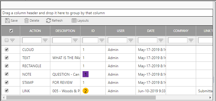
The flyout table lists all of the actions taken in the drawing area. All fields in the table are read only except the first column. Check or uncheck the boxes to show or hide that action layer in the drawing area. You can drag the divider bar left and right to resize the flyout and you can click the Pin button to lock the flyout in place. Click again to unpin it.