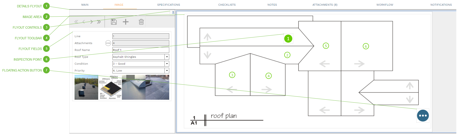
Use this tab to place inspection points on an image and view and edit data for each point. Adding and editing inspection points on this tab is the same as adding and editing them in the Details Table on the Main tab.
DETAILS FLYOUT
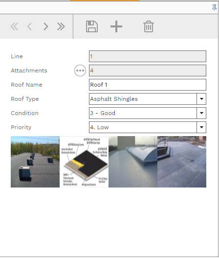
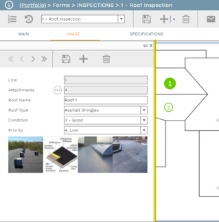
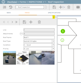
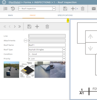
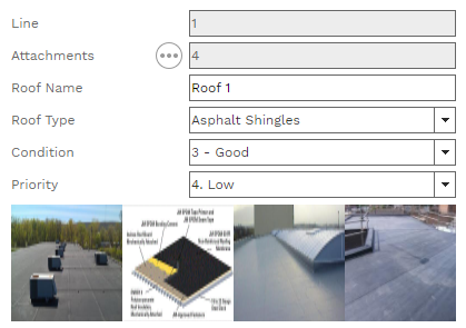
The flyout can be used to add, view, and delete information about each inspection point. The flyout can be opened, collapsed, and pinned using the Flyout Controls, described below.
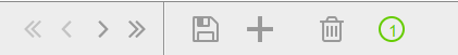
Navigation Buttons - Click these buttons to navigate through the table of inspection points. The left arrows are the equivalent of navigating up in the Details table on the Main tab. Right arrows equal navigating down in the table.
Save Button - Click this button to save edits to the inspection point fields
New Button - Click this button to add a new inspection point
Delete Button - Click this button to delete the inspection point. Note that this both removes the inspection point from the image area AND deletes the inspection point from the record. To simply remove it from the image area, see options described below in Inspection Point and Floating Action Button.
Inspection Point Placement Button - If the saved inspection point has not been placed in the image area, this button shows here. Click the button to open the Place Point dialog. Click OK in the dialog and then click somewhere in the image area to place the point. If the point has already been placed in the image area, this button does not show.
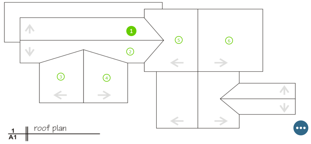
Each line in the Details table on the Main Tab can be placed on an image and is represented by an Inspection Point. Inspection points can be:
Clicked on to select
Clicked, held, and dragged to a new location
Right clicked to open a context menu
Options in the context menu include:
Add a Pont - If the Details Flyout is open, the new point can be edited and saved in the flyout. If the flyout is closed, the Inspection Details dialog opens.
View Details - Click to open the selected point in the Inspection Details dialog
Remove Selected Point from Image - Click to remove the selected point from the Image Area without deleting the point from the record.
Delete Selected Point - Click to remove the selected point from the Image Area AND delete it from the record
Change Image - Click to browse for a new image to display
Delete Image - Click to remove the image from the record, without selecting a new one
The selected Inspection Point looks different from all of the others in the Image Area. The selected point is larger and the color style is reversed. The Inspection Point color is selected in the header on the Main Tab.
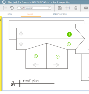
Click this button to open a context menu. The options in the menu vary, depending on whether or not an Inspection Point is selected. See the Inspection Point section above for information about context menu options.