Each asset record can contain an unlimited number of components grouped in an unlimited number of levels. Components can be other assets, inventory items, or be created on the fly. Assets and their components can be assigned an expected maintenance life cycle which PMWeb monitors for you. This is called “Predictive Maintenance”. The physical location of each component can be recorded, both in exact geo-coordinates and also in measurements of its position relative to a linear asset.
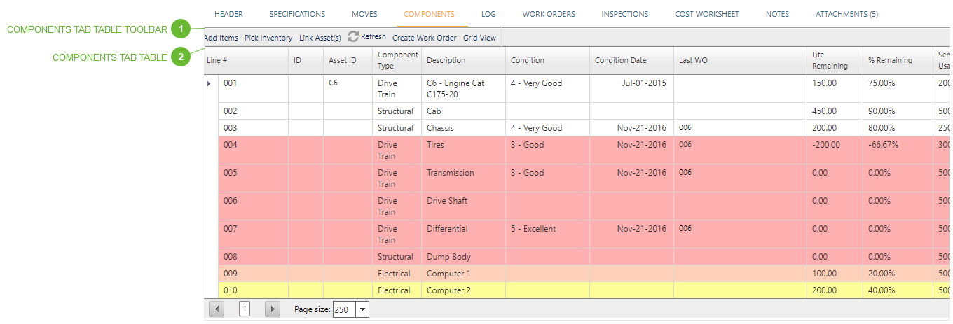
Note that components can be displayed in Grid View or in Tree View by clicking the toggle buttons in the toolbar:
Grid View – The standard PMWeb table view. In this view lines can be opened for editing.
Tree View – A special view showing components in a hierarchical tree with nodes that can be expanded and collapsed. Components are not editable in this view.
Each component can also be assigned a maintenance life expectancy, called a service interval. Service intervals can be based on elapsed calendar days or on usage, measured in any units you define. As calendar days go by or as usage data is logged into the system, PMWeb automatically calculates the life remaining in each component in the units you select and as a percentage. Color coded highlights – yellow, light red, dark red – alert you to components in need of maintenance. You can click on one or more components to select them (in either Tree List View or Grid View) and then click the Create Work Order button to immediately generate a PMWeb Work Order with all of the components attached. You can then record the work performed on each component, record inspection results, and reset the maintenance cycle for each as well.
Create Work Order Button - Select one or more components and then click this button. A new Work Orders record is created and opened with the selected components listed on the Work Orders Serviced Tab.
Important Note: Fields in this table are only available to edit when the tab is in Grid View mode. Items, inventory, and assets can all be added in either Grid View or Tree List View.
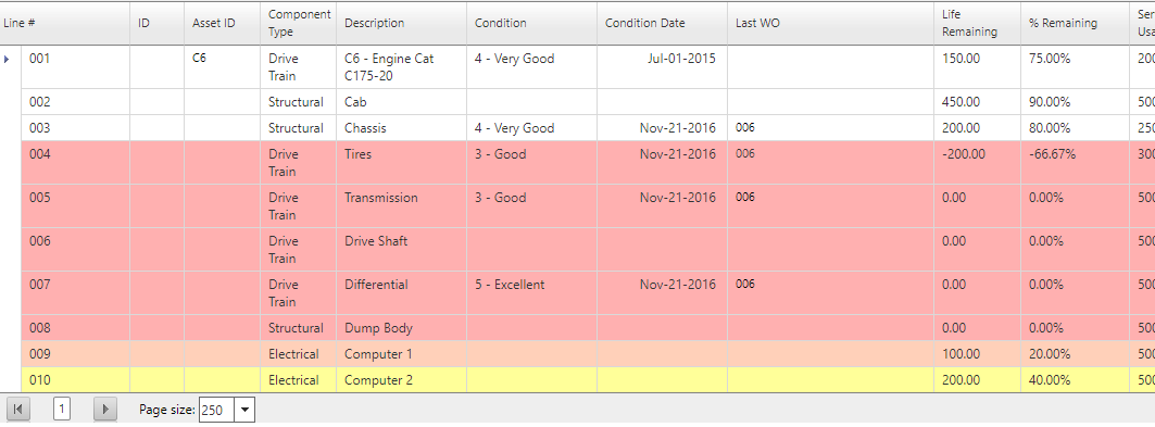
Lines in the table are color coded according to the % Remaining field. If Remaining % is:
Greater than 50 - White
Between 25 and 50 - Yellow
Between 10 and 25 - Light red
Less than or equal to 10 - Dark red
Note that lines that contain a Removed Date are not color coded according to the list above.
Asset ID Field - Read only. If the component was added using the Link Assets Button the ID of the asset appears here. Click the hyperlink to navigate to the record.
Last Work Order ID Field - Read only. The ID of the last Work Orders record where this component was either added, serviced or removed. Click the hyperlink to navigate to the record.
Life Remaining Field - Read only. If Service by Days is unchecked this field is calculated as Service Due Usage minus Current Usage in the header. If Service by Days is checked this field is calculated as Service Due Date minus Today.
% Remaining Field - Read only. If Service by Days is unchecked this field is calculated as (Life Remaining divided by Service Interval Usage) times 100. If Service by Days is checked this field is calculated as (Life Remaining divided by Service Interval Days times 100.
Service Interval Usage Field - Must be greater than or equal to zero.
Installed Usage Field - if the component was added through the Work Orders Serviced Tab, this defaults to the usage reading of the Work Order. If added locally the default is Current Usage in the header of this record, but it may be edited.
Last Service Usage Field - If added, serviced or removed from the Work Orders Serviced Tab, this defaults to the usage reading of the Work Order. If added locally the default is Current Usage in the header of this record, but may be edited.
Service Due Usage Field - Read-only. Calculated as Service Interval Usage plus Last Service Usage.
Life to Date Usage Field - Read-only. If Removed Usage is empty this field is calculated as Current Usage minus Installed Usage. If Removed Usage is not empty this is calculated as Removed Usage minus Installed Usage.
Service by Days Checkbox - If checked, usage is calculated by elapsed calendar days instead of log entries. The default is unchecked.
Service Interval Days Field - This field is used in calculations if Service by Days is checked. Must be greater than or equal to zero.
Installed Date Field - If the component was added through the Work Orders Serviced Tab, this defaults to the date of the Work Order but may be edited. If added locally the default is Today but may be edited
Last Service Date Field - If the component was added, serviced, or removed through the Work Orders Serviced Tab, this defaults to the date of the Work Order but may be edited. If added locally the default is Today but may be edited.
Service Due Date Field - Read only. Calculated as Service Interval Days plus Last Service Date.
Life to Date Days Field - Read-only. If Removed Date is empty this field is calculated as Today minus Installed Date. If Removed Date is not empty this is calculated as Removed Date minus Installed Date. If Installed Date is empty this field is empty.
Removed Usage Field - If the component was removed through the Work Orders Serviced Tab, the default is the Current Usage in the Work Order but may be edited.
Removed Date Field - If the component was removed through the Work Orders Serviced Tab, the default is the date of the Work Order but may be edited. If this field is cleared the Removed Usage field is automatically cleared.
Begin Field - Typically used in linear asset management. The point on the linear path where the component begins.
End Field - Typically used in linear asset management. The point on the linear path where the component ends.
Length Field - Typically used in linear asset management. By default this field is calculated as End minus Begin but it can be edited.
Direction Field - Typically used in linear asset management. The relative direction along the linear path in which Begin and End occur.
Lateral Offset Field - Typically used in linear asset management. The distance left or right from the center point of the linear path. Double click this field to open the Offset Dialog.
LO UOM Field - The unit of measure of the Lateral Offset field
Vertical Offset Field - Typically used in linear asset management. The distance up or down from the center point of the linear path. Double click this field to open the Offset Dialog.
VO UOM Field - The unit of measure of the vertical offset field
Radial Offset Field - Typically used in linear asset management. If the linear asset is circular (a pipeline, for example) this is the point on the circle where the component is located. Double click this field to open the Offset Dialog.
Latitude Field - Type a latitude in this field or double click to open the Google Address Dialog.
Longitude Field - Type a longitude in this field or double click to open the Google Address Dialog.
Elevation Field - Type an elevation in this field or double click to open the Google Address Dialog.
Asset Type Field - Read only. If the component is linked to an asset, the type appears here.
Stock # Field - f the component was added using the Pick Inventory Button the ID of the inventory batch appears here. Click the hyperlink to navigate to the inventory record.
Serial # Field - The data in this field defaults from the inventory item or equipment record but may be edited.
Lot # Field - The data in this field defaults from the inventory item but may be edited.